E-mail: zqdicheng@chinadicheng.com
Installation and pipeline connection of multistage centrifugal blower
1 Installation site
The blower installation site must be clean, dry and well ventilated. It needs to be installed indoors according to regulations. There should be enough space around the blower for maintenance, lubrication and disassembly.
2 Handling
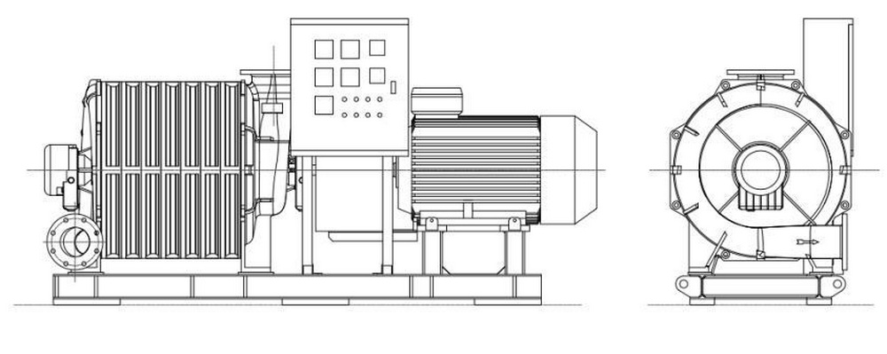
The blower is transported to the user's site, and the user is responsible for unloading, The whole machine can be horizontally forked through the welded base of steel structure (Fig. 1) or hoisted through the lifting lug of the base (Fig. 2). For bare machines, the sling position should be as close as possible to both ends of the blower (Fig. 3). The sling is not allowed to hoist the flange, main shaft or lifting ring installed on the bolt hole of the casing. During hoisting, the pull rod is easy to be squeezed and deformed, and the sling must pass under the pull rod for hoisting.

Fig. 1 Fig. 2 Fig. 3
3 Foundation
The advanced structural design, precise processing and manufacturing of the blower and the inherent running stability of the Centrifugal Machinery eliminate the need for large-scale foundation and a lot of on-site preparation; The unit must be placed on a solid and flat surface to support the weight of the unit. Concrete structure shall be adopted as far as possible to avoid the use of sandwich floor slab, narrow channel and hollow floor. An appropriate width shall be reserved around the foundation, and the foundation must be clean,
 The base is inclined horizontally in the direction of length and width, allowing 1.5mm/m to 3mm/m.
4 Installation
Each blower is equipped with different types of elastic damping pads according to its weight. Refer to fig. 4 for the mutual position between the damping pad and the blower base. In order to adjust the unit level during installation, a gasket with a certain thickness and the same size as the damping pad can be added under the elastic damping pad. It is not allowed to add the gasket between the base and the damping pad. For the oil lubrication system, The horizontal adjustment of the unit in the width direction is particularly important.
Anchor bolts can be used to locate the equipment, but the unit cannot be fixed by anchor bolts. Fixing the unit by anchor bolts or grouting the system will greatly increase the support hardness, which may increase the bearing vibration, which is counterproductive. No torsion is allowed between the anchor bolt for positioning and the base, and there must be a certain gap.

fig. 4
 The foundation is provided with foot bolts. Do not tighten them, but only tighten them by hand.
 Do not grout the unit base, otherwise the warranty will be invalid.
5 site piping requirements
The connecting pipe diameter at the inlet and outlet of all blowers must be large enough to obtain the maximum air capacity with the minimum resistance loss and reduce the additional loss caused by the inlet or outlet pipe diameter to the system. The additional weight of the pipe and connecting accessories acting on the blower flange will lead to poor alignment and internal wear, so do not act the weight of the pipe on the blower. An expansion joint must be installed between the blower and the pipeline system. The expansion joint is used to compensate for the misalignment of the pipeline. Generally, it is not recommended to use the control rod or limiting rod. If it must be used, do not tighten the two flanges too tightly, otherwise it will limit the thermal movement and increase the vibration amplitude. If only rigid soft joints can be used due to working conditions, and flexible soft joints cannot be used, The weight of rigid joints must be supported separately and measures shall be taken to prevent heat accumulation. Before the blower is connected to the system, the system pipeline must be cleaned first, and the residue in the pipeline will damage the blower.
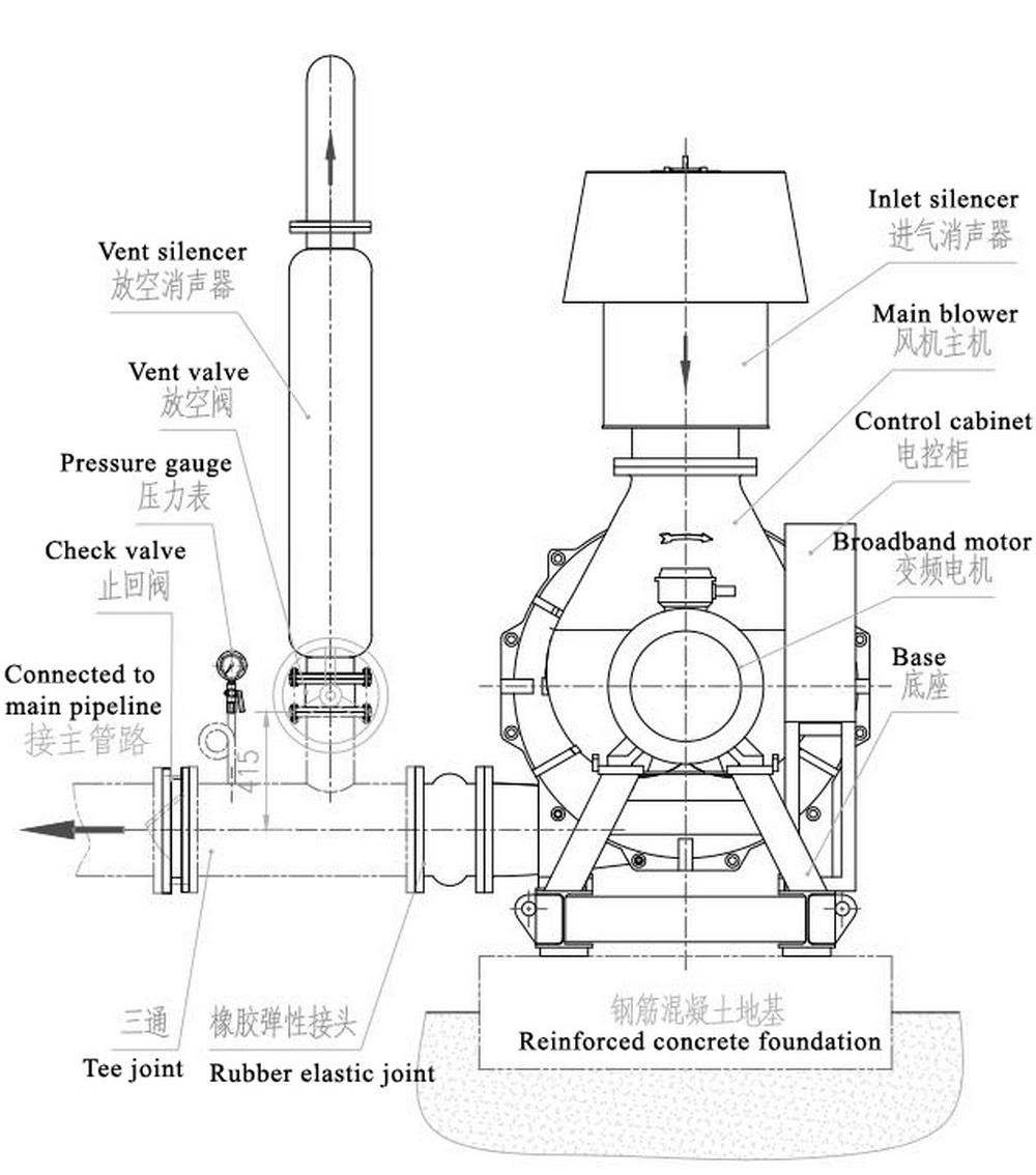
 Rubber elastic joints must be installed between the blower and the piping system.
6 Accessories
6. 1. The unit must be equipped with elastic damping pad, coupling and its accessories, and coupling protective cover.
6. 2 Recommended configuration
Considering the safety and reliability of the blower, the following accessories shall be provided at least:
a) Vent valve: used when the blower is started or stopped, or as an emergency relief valve to control air capacity in case of surge.
b) Check valve: in the vacuum system, the check valve must be installed upstream of all control devices in the inlet pipeline; In the blast system, the check valve must be installed downstream of the exhaust pipe element.
c) Inlet filter: install the inlet filter to prevent foreign objects from entering the blower. Abrasive, wet or large particles can damage the internal components of the blower and cause catastrophic failure. Generally, when the pressure drop of inlet filter exceeds 4kPa, it is recommended to clean or replace the filter.
d) If the user needs spare motor, elbow, muffler, filter, valve, electric control cabinet, elastic soft joint, combined common base, tee joint, shockproof pressure gauge and other accessories, please place an order separately.
e) The piping layout is as follows:

7 Coupling alignment
Blower alignment procedure: first, conduct cold alignment of coupling during blower installation; Secondly, start the blower until the blower temperature is stable (it usually takes 1.5 ~ 2 hours), measure the temperature difference between the inlet and outlet of the blower; finally stop the blower, add a certain thickness of gasket between the bottom foot of the casing and the bottom foot of the motor at the inlet side of the blower, and fasten it. Ensure that the concentricity of the two half couplings and the parallelism of the two end faces are not greater than 0.05mm. At the same time, considering the axial extension of the shaft, enough space should be reserved between the two half couplings, which can be strictly followed The data issued by the coupling manufacturer shall be implemented.
Inspection items before coupling alignment:
a. The base and foundation must be horizontal and smooth;
b. The pipe must be separated from the blower by elastic flexible joint;
c. The structural base of the blower must be installed on the elastic damping pad, grouting is not allowed, and the foot bolts shall not be tightened;
d. Check whether there are soft feet. The feet of motor and blower must be implemented to obtain more accurate alignment.
The blower host and the motor are connected and driven through the diaphragm coupling, and must be accurately aligned as far as possible to ensure trouble free operation and minimize vibration and subsequent premature wear of bearings, seals and couplings. Note that no vibration during startup does not mean good alignment.
There are many methods to align the coupling. It is recommended to use the dial gauge alignment method or laser alignment method. When using the dial gauge for alignment, please pay attention to the influence of the drop of the dial gauge at the highest and lowest points due to its self weight.
Each blower has been preliminarily aligned on a trial basis before leaving the factory. Before delivery, the middle section of the coupling and the diaphragms on both sides and other accessories have been removed and packed by the equipment. The lifting, movement and transportation of the equipment will also break its preliminary alignment. Therefore, the customer needs to carry out final alignment after installation.
 The final alignment of the coupling is the responsibility of the on-site installation Party of the blower. Vibration or other problems caused by the non final alignment of the coupling will lead to the loss of warranty.
When the centrifugal blower is working, there will be thermal growth, which will make the main shaft of the blower float on the exhaust side, break the original alignment, and shut down the blower for primary thermal alignment.
Copyright © Shandong Dacheng Machinery Technology Co., Ltd All Rights Reserved | Sitemap | Powered by 